A Fan Controller for the MFJ-4125 Power Supply
© Copyright 2009 Alan Bloom. All rights reserved
The
MFJ-4125
"MightyLite" is one of the least-expensive 12V, 25A power supplies available
(~$100). Unlike some switching power supplies it generates very little
electrical noise. It is very small (about 5.5 x 3 x 7 inches) and
lightweight (about 3 pounds) which makes it perfect for portable operation.
It got a good review
in QST.
The only complaint I have heard is that, while it may have very
little electrical noise,
some users feel
that acoustic noise is another matter. I don't find the fan noise to be
a problem as long as I keep the unit under the operating bench, but if
the power supply is sitting on the desktop right in front of me, indeed
the noise is quite noticeable.
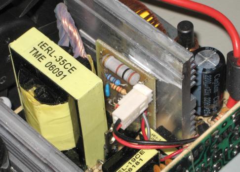
In addition, I discovered that the internal heat sinks get quite hot,
especially the one on the right that holds the rectifier bridge. After
15 minutes with a 20A load it reaches over 80 °C, way too hot to touch.
 The fan voltage measured about 10V in my unit before modification. The
new fan controller circuit lowers the fan voltage to about 6.7V at low
temperatures to reduce acoustic noise and raises it to about 12.9V at high
temperatures to improve the cooling. The graphic to the right plots fan
voltage versus sensor output voltage and the temperature that corresponds
to the sensor voltage. This circuit should be usable in just about any
12V power supply that uses a DC fan.
The fan voltage measured about 10V in my unit before modification. The
new fan controller circuit lowers the fan voltage to about 6.7V at low
temperatures to reduce acoustic noise and raises it to about 12.9V at high
temperatures to improve the cooling. The graphic to the right plots fan
voltage versus sensor output voltage and the temperature that corresponds
to the sensor voltage. This circuit should be usable in just about any
12V power supply that uses a DC fan.
 The curve of fan voltage versus temperature can easily be modified by
changing resistor values. R4 sets the minimum fan voltage at low
temperature. The slope of the ramped portion of the
voltage-versus-temperature curve is determined primarily by the ratio of
R3 to R1. Changing R3 changes the slope while keeping the right endpoint
constant. Changing R1 also changes the slope of the ramp, but while
keeping the left endpoint constant. Changing R2 moves the entire
ramp up or down without changing the slope.
The curve of fan voltage versus temperature can easily be modified by
changing resistor values. R4 sets the minimum fan voltage at low
temperature. The slope of the ramped portion of the
voltage-versus-temperature curve is determined primarily by the ratio of
R3 to R1. Changing R3 changes the slope while keeping the right endpoint
constant. Changing R1 also changes the slope of the ramp, but while
keeping the left endpoint constant. Changing R2 moves the entire
ramp up or down without changing the slope.
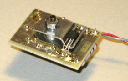
Construction
 This is a "no holes" modification — it's easy to restore the power
supply to an unmodified state if desired. While I used a small printed
circuit board, other construction techniques would work just as well.
PC boards may be purchased for $4.00 plus shipping and handling from
FAR Circuits. (Refer to the
"BLOOM FAN CONTROL" board in the "Repeater Controller & Station
Accessories" section.) Power is supplied via two wires
that connect the holes labelled "J1" on the new fan controller board to
the front panel +12V and ground terminals. The fan plugs into P1 on the
new board. To restore original operation, just plug the fan back into
the original motherboard connector.
This is a "no holes" modification — it's easy to restore the power
supply to an unmodified state if desired. While I used a small printed
circuit board, other construction techniques would work just as well.
PC boards may be purchased for $4.00 plus shipping and handling from
FAR Circuits. (Refer to the
"BLOOM FAN CONTROL" board in the "Repeater Controller & Station
Accessories" section.) Power is supplied via two wires
that connect the holes labelled "J1" on the new fan controller board to
the front panel +12V and ground terminals. The fan plugs into P1 on the
new board. To restore original operation, just plug the fan back into
the original motherboard connector.
 The right-hand heat sink (the one that gets the hottest) happens to have
an unused tapped hole in it that is perfect for mounting the temperature
sensor. It appears to be a metric 3.0 mm, which is nearly identical to
a 4-48 thread. To get good thermal contact between the sensor and
the heat sink I used a small metal half-round cable clamp that makes a
nice fit around the curved side of the TO-92 sensor package. You may
have to bend the clamp a little with a pair of pliers to get a tight fit.
The right-hand heat sink (the one that gets the hottest) happens to have
an unused tapped hole in it that is perfect for mounting the temperature
sensor. It appears to be a metric 3.0 mm, which is nearly identical to
a 4-48 thread. To get good thermal contact between the sensor and
the heat sink I used a small metal half-round cable clamp that makes a
nice fit around the curved side of the TO-92 sensor package. You may
have to bend the clamp a little with a pair of pliers to get a tight fit.
In the photo, the clamp is mounted to the board temporarily with a nut to
allow positioning the sensor for soldering.
After publishing this article I have learned that apparently MFJ has
changed to a heat sink with fins on both sides. The clamp no longer fits.
Gil K8EAG reports that he was able to mount the PC board using a piece of
rubber O-ring between the board and the sensor to press the sensor against
the heat sink. He used a 0.180-inch spacer. He also had to remove some
of the PC board on the side with the 2-pin connector to get enough
clearance with the small transformer on that side.
Perhaps an easier solution would be just to mount the board elsewhere,
mount the sensor on the heat sink with the clamp, and run wires to
connect the two.
Turn-on test
Be aware that while the right-hand heat sink is grounded, the one on the
left has full line voltage on it. Always turn off the power supply and
unplug it from the power mains before removing the top cover.
If you omit the U1 sensor IC at first, you can test the circuit to produce
a graph similar to the one at the top of the page. Use a pot connected
between power supply and ground or a variable-voltage power supply to
temporarily take the place of the sensor. Then install U1 and mount the
entire assembly in the power supply. As a final "sanity" test, replace
the top cover and run the power supply with a 15-20A load for several
minutes. After a minute or two you should hear the fan start to speed up
as the power supply gets hot. I find that the internal heat sink now
runs a little better than 7 °C cooler with a 20A load.
| Parts List
|
|---|
| 0.1uF capacitor
| Digi-Key | 490-3873-ND | C1
|
| 2-pin male SIP header | Digi-Key | WM4200-ND | P1
|
| TIP-29C TO-220 transistor | Digi-Key | TIP29CFS-ND | Q1
|
| 2N3904 TO-92 transistor | Digi-Key | 2N3904FS-ND | Q2
|
| 10K, 1/4W resistor | Digi-Key | 10KQBK-ND | R1
|
| 22K, 1/4W resistor | Digi-Key | 22KQBK-ND | R2
|
| 100K, 1/4W resistor | Digi-Key | 100KQBK-ND | R3
|
| 100 ohm, 2W resistor | Digi-Key | 100W-2-ND | R4
|
| 1.8K, 1/4W resistor | Digi-Key | 1.8KQBK-ND | R5
|
| 1K, 1/4W resistor | Digi-Key | 1KQBK-ND | R6
|
| MCP9701 temperature sensor | Digi-Key | MCP9701-E/TO-ND | U1
|
| PC board
| FAR Circuits
| Bloom fan control board
|
| 0.187" ID half-round cable clamp | Digi-Key | 8141K-ND |
|
| Mounting hardware | | 4-48 screw & spacer
|
Top view of silkscreen, copper on bottom.
Home page
N1AL 11/22/2021